Back to School: Electricity Basics and how they apply to your
Vehicles electrical system.
After my posting on the UBB I received a few emails with good suggestions for topics in
future articles. I received one email in particular that was really informative. Here is
the note I received from David Smith- the text in blue is my response to Davids thoughts.
Chris,
WOW!
You certainly spent allot of time on those articles.
I haven't really had the time to go over everything. But the content I have read is
good.
The trick is ensuring people know about this resource. I only found it from your
post asking if anyone had read it.
Comments:
Mini disc - I think they have the compression algorithm to a point
where it is virtually impossible to tell the difference
between the CD and MD. I tried with my home system, Digital recording to MD, and
could not tell the
difference. In a car? No way. I think the only thing you may loose is the
soundstage and imaging. Bass possibly.
Tell me how a car can have good imaging with all those internal chaotic reflections??
Impossible.
I think that with the renewed interest from Sony, and others MD is here to stay. I
would recommend the MD
head units over cassette.
I think the average person (myself included) would have a hard time
differentiating between CD and MD. Once you are in a moving vehicle I don't think anyone
would be able to tell the difference. I would also recommend MD over cassette but MD still
has a few drawbacks. MD players are still expensive. There are still few pre
recorded titles available. To record you own music you need an MD recorder/player at home
and these are also expensive. I think a better alternative would be to stick with CD only.
As Andrew has shown us, with the Shoot out CD, you can create your own collections with a
CD burner. Granted, the one Andrew used was likely beyond what normal people would use but
the principle is still the same- get a CD burner and a multi media package for your PC and
off you go! Assuming you already have a PC (I think nearly everyone in the
club has one)what does it cost to start recording your own CD's? Maybe $500 for a burner
and software (I'm guessing...:) ) You can buy indash CD players for as little as $200.00.
So for the same investment as a MD player for the car you can have CD quality and the
ability to create your own collections. Speakers - Placement?
This is tricky... The thing that gets me about front speaker placement
in the kick panels is that
most passengers have legs. Legs tend to get in the way from the speaker axis
to the persons ears. In
a small car like the TEL, I think that the tweeter down at the kicks cannot work, as there
is not enough space.
I have mine in the factory location attenuated 1.5dB and angled a bit outwards. The
windshield does reflect quite well.
The speakers aren't too harsh so it is not a problem. I think one of the best
improvements to the door/kick panel
mounting of a mid is the proper sealing of the speaker. This is mostly overlooked.
It's true that speaker placement is tricky, infact, very tricky.
That is why you must experiment to find the best location. When I used to compete one of
the judges told me that his car (a '91 Talon) had excellent imaging. He used 4 1/2"
coaxial speakers in custom kick panels. I have mounted tweeters in the kick panels of my
wife's Caravan and my brother mounted them there in his Regal. There is sufficient room
for a 1" tweeter especially if you use a surface mount eyeball. The real trick is as
David mentioned- finding the spot to avoid having the sound blocked by passengers legs.
As David mentioned proper sealing of a speaker is
important. If the sound waves from the rear of the speaker can mix with those from the
front you will get interference. For the door speakers you can buy foam like baffles
that you mount on the rear of the speaker. I would cut a small hole in the
back so that the baffle does not "chuff". I'm referring to the sound you
get when you breath in and out of a paper bag, the same could occur with these baffles. I
did this based on a recommendation from a pro shop and it seems to work well. Radio Shack
used to carry the baffles- I'm not sure if they still do or not.
Other thoughts on soundstage...
How many pop recordings are actually live recordings with a single directional mike that
would record an environment to recreate?
What kind of music requires proper recreation of a soundstage?
I'll bet that soundstage for the majority of the Rock/Pop stuff is non-existent. You
are not re-creating an acoustic environment.
Infact, with most recordings, there is no acoustic environment. Most of the pop/rock
music is made from layered tracks, either from
electronic instruments, or single instruments recorded in anechoic chambers.
So what IMAGE exactly are your recreating?
Some good points here. Yes I agree that most modern pop/rock
tracks are recorded via layering but the imaging is still there. I would bet that 95% of
recordings have the lead singer front and centre. How many recording have you heard where
the singer is only coming out of the left channel? The idea behind having good imaging in
the vehicle is to recreate having the singer still FRONT and CENTRE. With systems that
suffer from left/right bias the singer nearly always sounds like they are singing out of
either the left or right speaker.
For those people (me included) that listen to
classical or big band once in a while- imaging is even more important. With these
recordings you should be able to place the brass section, the strings and percussion
etc. and not have it sound like the entire orchestra is playing out your left speaker.
One of my favourite test disks is Dire Straits'
Brothers in arms. "Ride across the river" is a track in particular
that will demonstrate imaging and sound stage. In the background you can hear grasshoppers
etc. that should sound off in the distance. The soundstage should be very wide and deep.
The trumpet, for example, is off in the left background. Guitars primarily right
soundstage with left channel echo. Of course, Mark Knopfler is singing front and centre.
All of these traits should be evident in a good sounding car installation.
I think car stereos are great. In fact most of my listening happens in the car.
I couldn't live without the 10 Disc changer.
As for quality... My home stereo is much better. This is a given. Don't
misunderstand this.. I have been in some fantastic sounding
cars, but none approach the experience you get from a good home system. I don't
think that this fact can be disputed.
As for loudness.... 125 dB in the car is louder than my home, although my sub at home can
hit about 130dbA shown on the radio
scrap.. Not too bad for 2 X 10" in an isobaric configuration.
Most people are in the car when it is in motion. A car in motion generates a lot of
ambient noise - especially the TELs.
Unless you have a Lincoln, this is a big problem with dynamic music with very low to very
loud passages.. Some of the older Peter
Gabriel stuff is unlistenable in a moving car.. You don't detect half the stuff.
This is one of the draw back to car audio- cars move and
generate noise in doing so. Most competition systems will bump up the sub bass a
good 3 dB from 20 Hz to 80 Hz and gradually roll off the response at higher frequencies.
This is to help overcome those low frequency ambient noises. Adding soundproofing also
helps to block out ambient noise and to prevent resonance from interior panels. We'll
discuss setting up the frequency response and noise damping in later articles. P.S
Anything Over 110 dB is going to damage your ears! So use common sense when cranking it
up.
Suggested Topics.
Ambient noise and its affects on sound....
Mufflers, hwy noise, etc. Compare home at 45 dB, car hwy at 75dB+
Speaker efficiencies related to amplifier power, related to volume.
E.g... 80-90 dB in a home is quite loud.... It would take 100-110 dB in a car to
equal the subjective loudness.
Electrical terminology... Ohms law. Fusing requirements, wire recommendations, etc.
I have a chart of resistance of wire gauge vs. length. Too many people use these
huge power wires when it is not required.
I also have a chart of current capacity vs AWG that may be good to post.
A section on vehicle grounds, including common ground points in the car. Symptoms,
etc. This can be a major pain.
Tools of the trade.. I don't know if you provided this, but this would be good.
Sound Listening Advise.
How to set up a system.... Crossover frequencies, test discs, amplifier gain.
Loudness.. What does dB mean? Hearing safety.. Look at OSHA for information on this.
I hope to touch on many of these
topics at some point or another.
I think one of the most difficult things with any type of audio is evaluating speakers.
The only real way to evaluate speakers is in the
environment they are intended for. There have been studies that I have read
concluding that in a double blind test, on axis response
from a speaker could not be distinguished from the source. This test was performed
by a close miked speaker in an anechoic
chamber with an AB switch between source direct, and speaker. The test was performed
in the 60's. It really concludes that
environmental considerations are the single most important factor in a speaker's sound.
I agree 100%
I think this is a good resource. What you don't want to do is repeat allot of
information that has already been posted.
Make a direct reference to the faqs available from
rec.audio
rec.audio.car
These FAQs have a lot of information on the subject.
I think that for the best idea would be to provide SPECIFIC information about TEL
installs.
Good idea. However I only know the 1G well and I really
wanted this to be useful for any vehicle. I will use more examples with the TEL's in mind.
This includes where to route wires.
Where to mount speakers.
Common Rattles, and fixes.
Fusing locations. Power wire with information on fuel pump rewire.
Amplifier locations, crossover locations.
Recommendations on components, headunits, speakers, etc.
Specifics would be a great resource. I could help out with some tidbits of
information.
Keep up the good work.
Dave |
OK class today's subject is "electricity"!
I think we have all had some electrical theory at some point or
another- I know I had it in high school physics. In this article we'll talk about some
electrical basic and apply them to audio systems and automotive electrical systems. We'll
start off with the basics then move on to some more advanced stuff to see how it relates
to speaker installs and amplifier loading.
FIGURE 1:
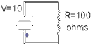 This is a very simple electrical circuit. We have a source of
electrical power, a path for the "electricity" to flow and a load that uses the
electrical energy. OK lets delve a little deeper into this simple circuit and see what is
going on.
This is a very simple electrical circuit. We have a source of
electrical power, a path for the "electricity" to flow and a load that uses the
electrical energy. OK lets delve a little deeper into this simple circuit and see what is
going on.
Consider first the "supply" of the electricity. We can see
that the above circuit has a supply voltage of 10 Volts- but what does this really mean?
Well, for each volt (V) there is difference of 1 coulomb (6,280,000,000,000,000,000
electrons) from the negative terminal to the positive- so in the above example there are
10x 6,280,000,000,000,000,000 more electrons on the negative terminal than the positive.
This potential difference is called the electromotive force (emf) and it's unit of
measurement is the volt. The more volts the bigger the emf and more electrons to flow in
the circuit and perform work for us. Once 1 coulomb of electrons has moved from the
negative to the positive terminal the potential difference will only be 9 volts and once
another coulomb has moved it will be only 8 volts and so on. It is for this reason
batteries "die"- the number of electrons that have moved from the negative
terminal to the positive is too many to perform anymore useful work. It is for this reason
the automotive electrical system uses an alternator. The alternator charges the cars
battery to keep the potential difference between the negative and positive terminal equal
to 12 coulombs of electrons or 12V.
Now we are really going to confuse you! It's easier to think of
electrical circuits when the electricity moves from positive to negative. However, we have
already shown that electrons move from negative to positive so what gives? Well, we
know have to get into the atomic level of our circuit! If you remember back to high school
physics each atom of a substance has a number of electrons orbiting the nucleus. If
the atom loses an electron there exists a "hole" that can be filled by another
electron. The following diagram might clarify somewhat.
FIGURE 2:
 . As each electron moves from the left to the right to fill
an open "hole" a new hole is created. So the "holes" appear to
move from right to left. Since an absence of an electron dictates a positive charge then
the holes can be thought of as positive charges. Now it should be apparent that if the
electrons move from negative to positive and the holes move opposite to the electrons, and
are positive, then positive charges move from positive to negative. Clear as mud
right?????From now on we will be assuming that the flow is from + to -. So if you look at
the first diagram above the flow shown is for electrons and is opposite from what we will
assume from now on.
. As each electron moves from the left to the right to fill
an open "hole" a new hole is created. So the "holes" appear to
move from right to left. Since an absence of an electron dictates a positive charge then
the holes can be thought of as positive charges. Now it should be apparent that if the
electrons move from negative to positive and the holes move opposite to the electrons, and
are positive, then positive charges move from positive to negative. Clear as mud
right?????From now on we will be assuming that the flow is from + to -. So if you look at
the first diagram above the flow shown is for electrons and is opposite from what we will
assume from now on.
In order for the "holes" to move from the positive plate
to the negative they must travel through a path that will conduct and not impede
their journey. Gold makes an excellent conductor because it has many orbiting electrons
that are available to move from one atom to the next. As we know though Gold is very
expensive and as a result is impractical to use for circuitry. Copper, on the other hand,
is relatively cheap and is also an excellent conductor-which explains why the majority of
wire is made from copper.
In figure 1 you can see that the path to the load (the resistor) and
back to the source appears to be made by wire connection. i.e. a wire is used to the load
and another used back to the source. In a vehicle this would be very impractical as you
would need a wire to each load and back to the battery. The load could be anything- turn
signals, starter motor, rear window defogger, radio etc. Imagine the amount of wire
needed! You would have twice as many wires in your car as you have now. So how did the
designers get around this? Rather simply actually! The return path from the load to the
battery is the metal of the car itself. So all the wire that would have been required is
reduced to one huge "wire". Now by doing this you eliminate a ton of wire but
you also introduce a bunch of problems. The worst of which is a ground loop and these play
havoc with the audio signals in your stereo system. We'll talk much more about these
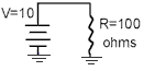
problems in other articles. The important thing to get out of this section is the fact
that the automobile uses a common return path. Figure 3 shows the interpretation of a
common return circuit. It still functions exactly the same way as the circuit in figure 1.
FIGURE 3:
Let's go back a little in order to discuss current. We talked
about Coulombs of electrons moving from the negative to the positive plate- well, when the
intensity of electrons flowing is such that when 1 Coulomb passes a given point in 1
second the electrical current flowing is 1 Ampere. The symbol for the current is (I) for
intensity and the unit of measurement is the Ampere. So, 1 Ampere = 1 Coulomb / 1 second.
Remember we said that the "holes" flow opposite to the
electron flow-therefore, 1 Ampere= 1 Coulomb(of holes) / 1 second.
Well, we've discussed the source, the path and current. We should
probably talk about the load before moving on. The load can be anything that
requires electricity to operate e.g. head lights, starter motor, ECU, speakers, amplifiers
etc. etc. The current required to operate could range from a fraction of an Amp
(milli-Amps), for items like engine sensors, to several Amps for items like head lights
and starter motors. Each load will impede the flow of current and is said to offer
resistance. The resistance of a load is measured in Ohms and the symbol is the greek
symbol Omega. The higher the resistance the less current will flow and vice versa. Infact
the very wire that the current flows in is resistive to current flow. The thinner the
gauge of wire the more resistive it is. An analogy would be water flowing through a
hose- you can't flow as much water through a garden hose as a large fire hose. The
smaller hose is more "restrictive" than the larger fire hose. It's for this
reason people upgrade the wiring going to their fuel pumps. The factory wire is rather
thin and will have a higher resistance than an upgraded larger gauge wire. The voltage
drop (loss) to the pump, caused by the wiring, will be less allowing it to run at a higher
voltage and spin faster and pump more fuel. The same applies to car audio. The bigger the
gauge of wiring used the less voltage will be lost to the wire itself allowing the
amplifiers, speakers etc. to perform better. Does this mean all the wiring should be
4 gauge to maximize performance? It is true that the voltage loss would be minimal but you
also have to take into practicality. Physical size of the cable, cost and weight would be
a few of the factors to account for. We'll look at selecting cable size when we get to
later articles. I will tell you that there are charts to use that tell you what the
optimum gauge should be based on length of run and current requirements. http://www.mobileaudio.com/ should have more
information on this if you can't wait.
Oh what the heck...here is the chart anyway...
Length of Run (in feet)
Current |
0-4 |
4-7 |
7-10 |
10-13 |
13-16 |
16-19 |
19-22 |
22-28 |
0-20A |
14 |
12 |
12 |
10 |
10 |
8 |
8 |
8 |
20-35A |
12 |
10 |
8 |
8 |
6 |
6 |
6 |
4 |
35-50A |
10 |
8 |
8 |
6 |
6 |
4 |
4 |
4 |
50-65A |
8 |
8 |
6 |
4 |
4 |
4 |
4 |
2 |
65-85A |
6 |
6 |
4 |
4 |
2 |
2 |
2 |
0 |
85-105A |
6 |
6 |
4 |
2 |
2 |
2 |
2 |
0 |
105-125A |
4 |
4 |
4 |
2 |
2 |
0 |
0 |
0 |
125-150A |
2 |
2 |
2 |
2 |
0 |
0 |
0 |
0 |
OK, we've talked about voltage, current and resistance. We can now combine that
knowledge into a basic electrical law known as Ohm's Law. There exists a relationship
between all three properties and knowing any two of them we can apply simple math to
figure out the third. So, Ohms Law in a nutshell is V=IxR. I.e the voltage
drop across a load is equal to the current flowing through it multiplied by the resistance
of the load itself.
Of course this can also be expressed as I=V/R and R=V/I
Using figure 3 as an example we can figure out the current flowing in
the circuit..We know V=10volts and R=100 Ohms therefore; I=10/100 or I=0.1 Amps. This is
more often than not expressed as 100mA (100 milli-Amps)
Each load will dissipate a certain amount of power and this too can be
easily figured out using another simple formula.
P=VxI and the unit of measurement is the Watt. Once again using figure 3 we can deduce the
power dissipated is;
P=10x0.1 = 1watt Once again, the formulas can be manipulated
mathematically such that P= (VxV)/R=(IxI)xR.
Where is this of use to use? Well lets assume you have some fog lights
that are rated at 100 Watts and want to know how much current it will require from the
battery. You can easily figure it with the knowledge we have just learnt. We can assume
the voltage from the car battery will be about 12V and we know the power dissipated is
100W therefore; I=P/V=100/12=8.3 Amps. Therefore, you will likely need a 10Amp fuse to
hook up the lights.
One thing I should mention now is the fact that we are dealing with
direct current (DC) analysis at the moment. Things change somewhat when we work with
Alternating Current (AC). Remember those sine waves from article
four? Well they are AC in nature so we will have to change our method of thinking
shortly when we start working with resistance's offered by speakers etc.
Wiring Configurations:
Note all the diagrams were borrowed from :
http://members.xoom.com/jimas/ser_par.html
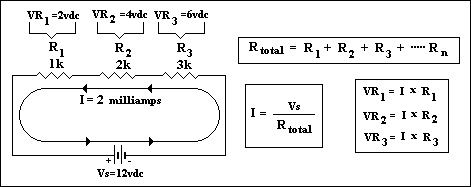
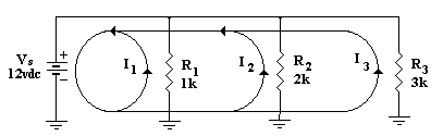
The circuit in figure 1 is know as a series configuration because there is only one
path for the current to flow. Here is another circuit that is wired in series. The primary
thing to remember is that the current value is constant in a series circuit.
figure 4:
 Solving unknown values in any circuit really
boils down to working with a) what values you do know b) It's properties (serries,
parallel, combination) c) basic mathematical formulas
Solving unknown values in any circuit really
boils down to working with a) what values you do know b) It's properties (serries,
parallel, combination) c) basic mathematical formulas
Consider the circuit to the left. We know the voltage and individual
resistance values, we know it is a series circuit and we know some basic formulas so, with
some thinking we can solve other "unknowns" about this circuit. In this example
the current is given but you can easily find it if it wasn't by using ohms law. In a
series circuit the total resistance is the sum of the individual ones. In this case it's
1K+2K+3K or 1000+2000+3000 i.e. 6000 (6K) Ohms. Now using Ohms law we can calculate the
current by dividing the supply voltage by the total resistance. In this case it works out
to 0.002Amps or 2 milliamps. Now we know one important fact- the current flowing in this
Series circuit is 2milliamps. Why is it important? Remember the property of a series
circuit- current is constant, therefore that 2milliamps has to flow through each resistor.
Now we can apply ohms law once again, to each resistor, to calculate the voltage drop
accross it. Applying the formula for power (P=VxI, and it's derivatives) we can
calculate both the power dissipated in the individual resistors and the total power
dissipated.
Series circuits are not widely used in the automotive environment because if the
circuit breaks anywhere or a component opens then the circuit is dead as no current can
flow. An example would be the old strings of Christmas tree lights- when a single bulb
blew then the entire string was dead and it was a real pain trying to find the dead one.
Parallel circuits are the most widely used configuration as there are multiple paths for
current to flow. We'll look at them now.
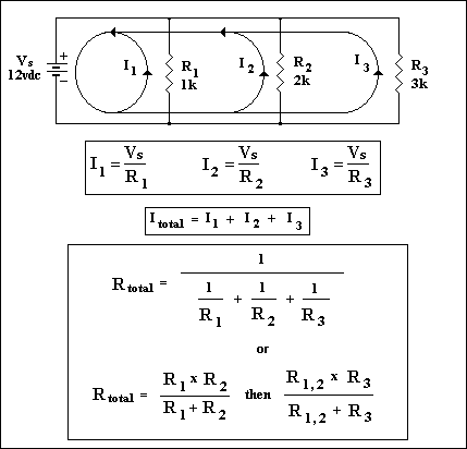 This is a parallel configuration because there are
multiple paths for current to flow. The main thing to remember about parallel circuits is
that voltage is constant across each leg. However, Ohms law still applies and we can
calculate unknown values. The hardest thing to calculate is the total resistance but the
formulas shown in the diagram should help. You'll know that you are correct if the total
resistance is smaller than the smallest resistance in the circuit. In this case the total
resistance will be smaller than 1K Ohms. It works out to be 545.5 Ohms using the formula
provided.
This is a parallel configuration because there are
multiple paths for current to flow. The main thing to remember about parallel circuits is
that voltage is constant across each leg. However, Ohms law still applies and we can
calculate unknown values. The hardest thing to calculate is the total resistance but the
formulas shown in the diagram should help. You'll know that you are correct if the total
resistance is smaller than the smallest resistance in the circuit. In this case the total
resistance will be smaller than 1K Ohms. It works out to be 545.5 Ohms using the formula
provided.
Using Ohms law again we can calculate the current flowing in each leg
and then sum them all to find the total current demand on the supply.
OK let's figure that out...I1=12/1000=12mA, I2=12/2000=6mA, I3=12/3000=4mA and the total
current is I1+I2+I3=22mA Using the power formulas we can calculate the power dissipated by
each resistor and then sum the individual values to find the total. In this example
P1=VxI1=12x0.012=0.144W, P2=VxI2=12x0.006=0.072W, P3=VxI3=12x0.004=0.048W therefore
Ptotal=P1+P2+P3=0.264W. We could have also found Ptotal by using
Pt=VxItotal=12x0.022=0.264W
In the automotive world nearly everything is wired in parallel. Each resistor, in the
diagram, would be a load of some kind-maybe a tail light or starter motor etc.
 I've redrawn the circuit to show the common return as
it would appear in automotive diagrams. The calculations are exactly the same however.
Ignore the arrows on the direction of current flow as it shows ELECTRON flow.
I've redrawn the circuit to show the common return as
it would appear in automotive diagrams. The calculations are exactly the same however.
Ignore the arrows on the direction of current flow as it shows ELECTRON flow.
e last configuration we'll look at is the series-parallel
circuit-which is just a
Thcombination of the two we've already looked at. The trick is to
use the knowledge we've learned so far and take bits and pieces to try and solve unknown
values.
Consider this circuit.
 As you can see part of the circuit appears to be
parallel and part series. Ohms law STILL works! You can find voltage, current and power
through each resistor if you think logically and use the formulas we know. We're not
going to solve the values in this example but we'll discuss a logical path to take
to go about solving the values. First combine R3 and R4 in to one value known as R34 using
the formulas given in the parallel circuits. Now you could redraw the circuit as a simple
series circuit replacing R3 and R4 with a single calculated value R34. You'll notice you
now have a simple series circuit. What do we know about Series circuits? Current is
Constant! It might be an idea to find this value. Simply add all resistor values to find
Rtotal =R1+R2+R34 and divide this into Vs to get Itotal. Now you can use Ohms law to find
the voltage drop across R1 and R2 and using by using; P=VxI find the power dissipated. Now
we have to solve the values for the section we simplified i.e. R3 and R4. Redraw the
original circuit and fill in all the values we know already. We know everything except the
values for the parallel section. What do we know about parallel circuits? Voltage is
constant! We know the voltage drop across R1 and R2 and we know the total voltage supplied
therefore to find the voltage across the parallel circuit section simply subtract
(Vr1+Vr2) from Vs (Vs=Vr1+Vr2+Vr34). Now we can use Ohms law again to find the current
flowing through R3 and R4. We now know the voltage so it's just a matter of dividing
this voltage by each resistor value for R3 and R4. Power can now be calculated using any
of the power formulas.
As you can see part of the circuit appears to be
parallel and part series. Ohms law STILL works! You can find voltage, current and power
through each resistor if you think logically and use the formulas we know. We're not
going to solve the values in this example but we'll discuss a logical path to take
to go about solving the values. First combine R3 and R4 in to one value known as R34 using
the formulas given in the parallel circuits. Now you could redraw the circuit as a simple
series circuit replacing R3 and R4 with a single calculated value R34. You'll notice you
now have a simple series circuit. What do we know about Series circuits? Current is
Constant! It might be an idea to find this value. Simply add all resistor values to find
Rtotal =R1+R2+R34 and divide this into Vs to get Itotal. Now you can use Ohms law to find
the voltage drop across R1 and R2 and using by using; P=VxI find the power dissipated. Now
we have to solve the values for the section we simplified i.e. R3 and R4. Redraw the
original circuit and fill in all the values we know already. We know everything except the
values for the parallel section. What do we know about parallel circuits? Voltage is
constant! We know the voltage drop across R1 and R2 and we know the total voltage supplied
therefore to find the voltage across the parallel circuit section simply subtract
(Vr1+Vr2) from Vs (Vs=Vr1+Vr2+Vr34). Now we can use Ohms law again to find the current
flowing through R3 and R4. We now know the voltage so it's just a matter of dividing
this voltage by each resistor value for R3 and R4. Power can now be calculated using any
of the power formulas.
There! As you can see it is not that difficult to use Ohms law. You
just have to break the circuit down into a simpler parallel or series circuit and solve
for values which can be used to find other unknown values when you look at the original
circuit. OK Now lets look at how this all applies to audio systems.
Ohm's Law and Audio Systems:
You would most likely use what we've learned so far to calculate the speaker impedance
to an amplifier channel. There are some things we should probably discuss before we get
too far into this portion of our article. If you recall from article 4
we saw that it was the speakers voice coil that was connected to an amplifiers channel. A
coil (as in "Voice coil") changes it's resistance with different frequencies.
This "resistance" should actually be referd to as an impedance as resistance is
usually a term used for pure resistive loads. Coils and capacitors are not pure
resistive-their "resistance" changes with frequency. Another term you may hear
is reactance. Inductive reactance is the impedance at a specific frequency for a
coil and capacitive reactance is the impedance for a capacitor at a specific frequency.
The unit of measurement for both is still the Ohm but instead of 'R' as the symbol
for resistance we use 'Xl' for inductive reactance and 'Xc' for capacitive reactance. We
don't need to worry too much about these reactances when determining amplifier load but
they do play a major role when designing crossovers. We'll work on a few examples a bit
later on just so you can get an idea of how frequency affects the impedance value.
OK back to load calculations.....When you buy a speaker it is normally
given a nominal value for the D.C impedance. These values are normally either 4 or 8 Ohm
but some are available in 6 Ohm values. Why the different choices? Well, the
configuration you use them in will play a role in your decision as to which Ohm value you
should buy. This nominal value is about 1.33 times (EIA standards) the actual DC
resistance of the speaker i.e. the approximate value you would read if you used an ohm
meter to measure the resistance of the coil.
We hook speakers up to the amplifiers using circuit configurations we
have already looked at namely either in 1) series 2) parallel or 3) series parallel. What
does this mean then? Answer: OHM"S LAW STILL APPLIES!!!
Let's consider a practical example: Let's say you have a dedicated
sub woofer amplifier to power the subs. It might have the following specifications- 50Wx2
into 4 Ohms, 125Wx1 into 4Ohms or 150Wx1 into 2 Ohms. How do you interpret this? If you
use both channels to power speakers then you can get a total of 100W (50Wx2)power in to
the speakers. However, if you were to combine both channels into one one bigger channel
(known as bridging) then you can get more power output. We'll look at bridging in detail
in later articles. What we want to concentrate on in this article is how to configure the
speakers to get the most power output. In our fictitious amplifier the most power output
is noticed when the speakers are configure to represent a total impedance of 2 Ohms.
So the idea is to wire the speakers to get a total impedance of 2 Ohms. We'll use four
different examples going from using one speaker to two to three and finally to four.
One speaker:
It's rare that you will find a 2 Ohm speaker so in most cases you will
only be able to get a 4 Ohm impedance which means your amp will put out 125 Watts into
this single speaker. However, if your single speaker has DUAL voice coils then you can
wire them as if you had two speakers and get a 2 Ohm load. This is accomplished by wiring
the voice coils in parallel. (+ to + and - to -).
figuring out the final resistance is actually quite easy if all
the speakers you are connecting together have the same impedance (4,6
or 8 Ohm).When connected in series (+ of one to - of the other) you simply add the
impedance's. So, two 4 ohm speakers in series is an 8 Ohm total impedance. Three in series
is 12 Ohms etc. In a parallel configuration you take the impedance of one speaker and
divide it by the total number of speakers you are connecting. Two 4 Ohm speakers connected
in parallel will yield a total impedance of 2 Ohms (4/2 i.e. 4 ohms/2 speakers). Four 8
Ohm speakers in parallel is a 2 Ohm total impedance (8/4). This rule ONLY applies to
combining speakers with the same impedance.
Two speakers:
With two speakers (or one dual voice coil speaker) we have a few
options. If we want to use 4 Ohm speakers then when combined in parallel the amplifier
will see a total impedance of 2 Ohms and the maximum power will be seen. Combined in
series the total impedance will be 8 Ohms and the power out put of the amp will be
much less. With 8 Ohm speakers the total impedance will be 4 Ohms in parallel and 16 Ohms
in series. As you can see knowing at what impedance the maximum power is realized
and then combining the correct impedance speaker(s) can have a huge affect on the power
output from the amplifier. Now if you used two dual coil speakers you would try and
configure them to get a 2 ohm total impedance to maximize the power. We'll save this
configuration until we look at combining 4 speakers together as it will be the same.
Three Speakers:
Combining three speakers together is normally not a good combination
with 4 ohm speakers as the impedance will be too low if connected in parallel or too high
if connected in series. With 8 ohm speakers you could hook them in parallel and end up
with a total impedance slightly higher than 2 ohms (8/3 to be exact). Now you could combine
two 8 ohm speakers in parallel then put them in parallel with a 4 ohm speaker to get the
ideal 2 ohm load. However, this is not recommended because the 4 ohm speaker will twice as
much power as the parallel combination of the 8 ohm speakers.
There are some manufacturers that now offer 6 ohm speakers so that when
you use 3 of them in parallel you will get the ideal 2 ohm load.
Four speakers: (or two dual voice coil speakers)
With 8 ohm speakers you can hook them all in parallel and get a 2 ohm load (8/4=2). with 4
ohm speakers the best we can hope for is a total load of 4 ohms. To accomplish this we
hook two speakers that are wired in series with each other in parallel with another two
speakers that are also wired in series with each other. Mathematically we can simplify the
"circuit" by assuming we now have two 8 ohm speakers in parallel with each
other. Therefore we have (8/2=4) ohm total.
As you can see Ohms law still works with speakers if you use the nominal speaker
impedance in the calculations i.e. 4,6 or 8 ohm (in general). However, once the frequency
of the music is introduced the overall impedance to an amplifier can change significantly.
We'll have a look at this briefly now. It will be covered in more detail in later articles
when we look at crossovers.
Frequency and Impedance:
One of the speakers main components is the voice coil. The DC value of this coil is
what is used to give us the nominal speaker impedance. The nominal impedance is about 1.33
times the actual DC value. So, a 4 Ohm speaker is really 4/1.33 Ohms.
Once the speaker starts to play music though the impedance
value will change depending on the frequency at that instance in time.
The impedance at that frequency is called the inductive reactance (Xl) and is
calculated using this formula
Xl=2(pi)FL where pi is 3.14blah blah blah, F is frequency and L is the inductance value of
the coil.
L and pi are constant and do not change therefore the variables are Xl and F. We can
see that if the frequency increases then the inductive reactance increases also. When the
frequency decreases then the inductive reactance also decreases.
The nominal speaker impedance is a guide that you use to figure out the
loading on an amplifier. Amplifiers are not designed to play dc voltages or very low
frequencies (approaching 10Hz or so). Infact, some amplifiers come with a subsonic filter
to cut these dangerous frequencies out. Why dangerous? Well, when you start loading down
an amplifier its tolerance to low loads decreases and you can often blow a fuse. In our
fictitious amplifier example we said it could provide 150W into a bridged 2 Ohm load. The
amplifiers channels, when used in a bridged configuration, actually see half the
impedance. In this case that will be 1 Ohm (nominal). Now if you apply the formula we have
above you can see that if the frequency drops too low the inductive reactance of the
speaker will drop also. If it drops too low the load on the amplifier will be too great
and you could either damage the amp or blow a fuse. You generally see this problem with
amplifiers that are of cheaper construction or not designed for extreme low impedance's. I
remember a long, long time ago my brother had a 500W Pyramid amplifier that was supposed
to be stable into 2Ohms. We hooked up two 4 Ohm speakers in parallel to get a 2 Ohm load
and then bridged the amp to power this load. The speaker protection circuit came on all
the time and at the time I didn't know why....Later I realized that the amp was 2 Ohm
stable but that was per channel. In the bridged configuration the amplifier saw a 1 Ohm
load per channel and so the protection circuit came on. When we used a single 4 Ohm
speaker it worked most of the time. It cut out on very low bass notes likely because the
impedance dropped too much for the amp to handle.
We'll look at amplifiers in much more detail in the next article.
Well I think that's about it for this article. I hope you learned
something! Remember to email me with corrections or differing thoughts on the subject.