Intake Leak Testing, and the Throttle Body Shaft Seal Replacement
|
Last Modified:
2014-10-30 |
Update: 2006 07 15
Added a bunch of little updates, particularly on where to look for leaks,
and things to look for if you have an aftermarket sheet metal intake of some
sort. Fixed some typos.
Update: 2006 05 11
Philip Spigelmire - Sent me updates for the 1990 throttle bodies, that are
apparently different than the rest of the years. One of the seals is smaller.
Read the whole thing first, but right at the end, I've added a section just for
the 1990 model year. To his credit, he sent me this info in February of 2004,
but I just found it today.

Update: 2003 12 11
Added a few suggestions and corrections.
Update: 2004 06 22 (from Alex)
FYI, NAPA doesn't seem to be able to get these seals anymore and Pep Boys, while
having the number listing, can't order it and told me "I think it has been
discontinued."
I checked Kamandirect and they list the seal as unavailable.
I finally found a place that can order it from the manufacturer and should
have them to me in a week. The reason I am even telling you this is cause it is
a national company, Motion Industries, with retail stores all over the country
and Canada:
http://www.motionindustries.com
They want $5 per seal + shipping and they will do whatever shipping you are
willing to pay for.
Let me start off by saying, that while this is a fairly simple process, it is
also fairly detailed, and should not be attempted with a monkey wrench and a
pair of pliers. I also take NO responsibility for anything you may break, damage
or destroy, or for any warranty you may or may not affect on the vehicle in
question.
This VFAQ was written after the fact, so you should at least read the entire
thing once, prior to attempting it. It only took about an hour to do the job,
pictures included, but YMMV.
That all being said, are we ready?
Many thanks to Steve Kinnaird, aka Captain Torque Steer of the Kinnaird
Modelling Academy... as he has provided
the car for the pictures, as well as the lovely hand modelling.
Thanks also go out to the members of Club
DSM Canada for hosting this VFAQ for us, and to Tom Stangl for
the main index.
Testing
Part One, deals with how to test for a leak, if you have not already done so.
You may have many leaks, in addition to your shaft seals. Most people, find many
leaks, and it simply becomes a question of "correct, and re-test".
Simply put, you have to plug the intake of the turbo, and then pressurize the
rest of the system... listening for leaks.
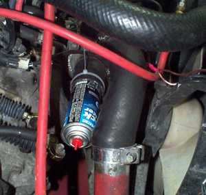 |
As you can see here, we have used a bit of rad hose, a similar diameter
metal can, and a couple of clamps to seal the inlet to the turbo. (clamp
the hose onto the turbo inlet, and then clamp the hose around the can to
make it into a big plug)
Rob Strelecki has mentioned, that Home Depot carries a nice coupler,
just about the right size for this, or any coupling process.
FERNCO #1056-22 -- comes with coupling and two clamps.
In recent tests, on my own car (20G), I have found that a Becks beer
bottle fits nicely into the silicone coupling on the turbo inlet.
After that, tee into one of the vacuum/pressure lines on the engine,
and pump in some air. I now prefer to tee into the BOV line, running
from the intake to the BOV. This ensures that the intake is getting max air
(it's a larger nipper) and that the BOV is seeing the pressure as well, so
that it will stay closed. (just like when the car has boost) |
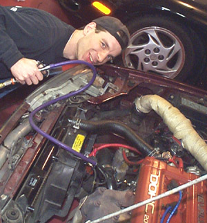
| As you can see at the end of the purple hose that our local test
monkey is holding, we have tee'd into the BOV line.
This is an easy line to get at, and functions well for our purposes.
the other end of the hose is going to a manual air trigger, which is
in turn being fed by an air compressor. Be careful where the regulator
on your air compressor is set to... you wouldn't want to pump 100 psi
into your intake. We set it for 25psi when flowing.
Recently, I have started using a 0-30psi inline air regulator. These
are NOT hard to get, most stores that either sell air tools, or painting
supplies, have them, for use directly on the bottom of paint or
powdercoating guns. Mine came with a little gauge on it as well, so I
can see exactly how much pressure I am putting it, how the intake is
responding, etc, right in the engine bay. Well worth the investment.
That's it... listen, feel, look, for leaks. You'll likely have a few.
Have a buddy watch your aftermarket pressure gauge in the car, to see
how much pressure you can hold, and this will help gauge how your
repairs are coming along, as you eliminate the leaks. For example, if
you can see 20psi under the hood at the regulator, but only 17 at the
dash, then you're losing air. The closer you can get, the better. It
is natural, that a small amount will leak out the tailpipe, but cap
other things, like the crankcase vents, if you can. |
 |
Sheet Metal Intakes
These are very popular these days, some also installing them with phenolic
spacers, to reduce heat transfer from the head.
Make sure, if you have a spacer, that the bolts and stud nuts are very tight.
Phenolic is hard stuff, but, not as hard as aluminum. I have noticed bolts and
nuts working loose. At this point, I don't know if it's heat cycling, shrinkage
of the phenolic, or just vibration. In any case, I've tightened them up "good",
and added locknuts to the studs.
One brand of intake in particular, that is VERY popular, has been
known to develop cracks in the welds. Look for leaks, around the joints and
welds. (I had 5 in mine, and have repaired welds on two others now)
The manufacturer has specified that if you contact him, he will repair the
cracks. But, if you don't have the time to wait for that, consider other
options. On mine (a very early beta product), three of the leaks were welding
fissures, or, defects in the weld, that were acting as vent points.
I already had the intake on the car, and it was also polished and powder
clear-coated, so I didn't want to remove it and start welding again. I mixed up
some 5 minute Epoxy, and coated the leaks, after cleaning the spot thoroughly.
They now, no longer leak at all. The epoxy has excellent bonding properties, and
my intake never gets very hot.
Another member also suggested "sand it, and apply some JB weld", but I don't
know how well JB Weld works with aluminum. (no experience with it)
The best option, of course, is to have the manufacturer repair the intake,
under warranty. I've heard, that their newer ones, come with extra structural
supports, to try and prevent the cracking.
It would be nice if they would also pressure test them, but I don't think
they're setup for that. You might want to try, before bolting everything back up
again.
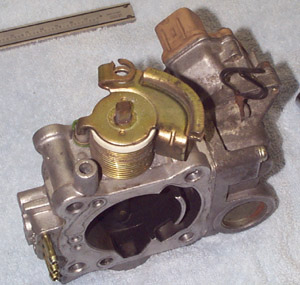
Throttle Body Shaft Seal Leak
This is likely why you're here reading this, so if you're still in the mood
to double check yours, listen around the throttle body. It's in the circle
below, roughly speaking.
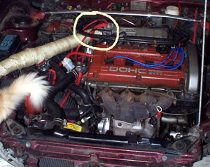
Please excuse the fuzzy tail, the cat just couldn't avoid helping us. Who
said we couldn't ever get a pussy on the hood...

As you provide pressure into the system, you will hear it leaking from this
general area. If you then manually rotate the throttle plate (or have the buddy
in the car step on and off the gas) you will hear the sound changing. This is
the leak around the shaft seals.
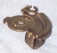
The problem with these things, is that they're simple rubber seals, bonded to
a metal ring. Over time, the rubber they used, gets tired from the heat, oil,
etc, that it's exposed to, and just goes rock hard. As you'll see later on, the
residue it leaves on the shaft as it's breaking down is terrible to try and
remove. The rubber is now like hard plastic, as you will see if you go on to dissect
it. They were likely not ever even thought of as much of a problem in design, as
they're definitely a long-term wear item that most customers would never notice.
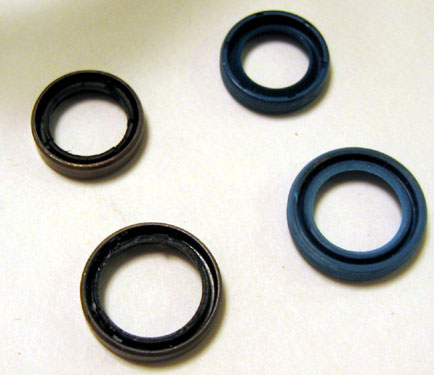
So, assuming you have purchased a pair of 14mm x 10mm x 4mm (or 3mm) shaft
seals, and are ready to proceed, let's get going.
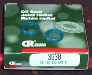
| As an aside, Craig Berndt did some looking and has found a place where one
can obtain the seals. I was purchasing them from a local supplier in my area,
but wasn't sure whose make they were, only that they worked. Craig says that
they are available from Chicago Rawhide, part # 3930 CR 10x14x3 HM4 R. He
also has suggested using www.kamandirect.com
as a source to purchase them. Steve Piette also emailed to say that NAPA can get them as well, using the
above CR part number.
John Novo provided this source, and these images of the ones he
bought from them.
www.kamandirect.com
I cannot speak for any other sources, or the seals from this location, as I
have not tried them, but people assure me that they are the same.
|
 |
Parts Removal
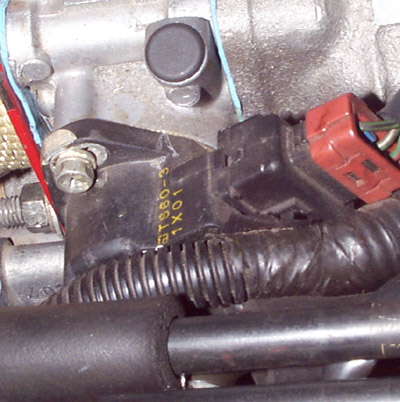
You will need to get at the TB.
Therefore, remove things that are in the way, including the upper intercooler
pipe, and possibly the battery, depending on the year of your car, and your
patience with getting tools under the TB elbow.
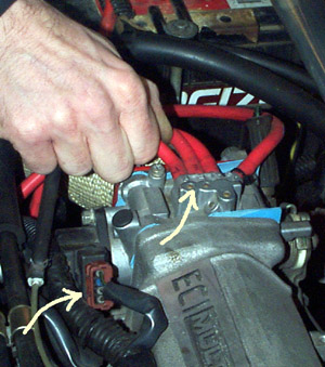
Disconnect the ISC (idle speed controller) motor electrical connection, under
the TB, on the passenger side of the car. It's a multi-pin plug, and has a
little plastic spring release, so don't just yank it off.
Remove the wire to the "throttle plate closed" sensor. This is
located on the rear side of the TB, and is ONLY on the 1G cars.
Remove the two coolant hoses going into the lower side of the TB. Make note
of which one is which, so that you can clearly connect up the correct ones again
when finished.
| On the top front side of the TB, is the TPS (throttle position sensor) and
it's connector. This one is a bit of a bugger to get off, as the clip spring
holding it on is complex to get off without breaking. Have a look around it's
base, and figure out which side of the spring clip to pry with a screwdriver to
get it loose. Once loose, the plug comes off.
Do not remove the TPS at this time... just the wire connection to it.
Label and then remove the hoses going to the top of the throttle
body. |
 |
 |
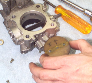
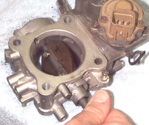
Reach behind the TB, and find the throttle cable. You will have to un-hook
this cable from the throttle plate wheel. The easiest way to do this, is to
crank the throttle plate open with your hand, and then fiddle with the cable to
get it rotated around and out. It links in, like the cable on the end of a
bicycle hand-brake.
If you're having problems with it, have a look at some of the pics later on,
to get an idea of what you're dealing with.
It's the thing to the left here...
|
Removal
Unbolt the four bolts holding on both the TB Elbow and the TB itself, if you
have not already done so to remove the UpperIC pipe.
Take great care in removing both items, so as not to damage the gaskets. If
damaged, they should be purchased and replaced, or replacement ones cut from
gasket material.
Once off, clean it up, and move to the workbench.
Disassembly
First things first, and very importantly.
Get a pad of paper and a pen out, and keep them handy. A good part of this
procedure is simply re-assembling what you have taken apart. You will be much
better off, if you make a few notes as you go, as to which way things go, and
which way they came off. Trust me.
 |
Mark the TPS and the housing next to it, in SEVERAL places around the outside
of it. (use a scribe or similar permanent marking device)
This is to ensure that
you can get it back EXACTLY where it was on the TB, when re-assembling it.
Without these markings, it will be very hard to get it right on your own, and
you may end up having a lot of problems. (link below, to help if you screw it
up)
Move any hoses and wiring harnesses out of the way, but you shouldn't have to
disconnect anything more.
As you can see, we did it while the TB was still on the car the first
time, but I would now recommend marking it up after you take the TB off
the car, and in that way, you can mark it in MULTIPLE places around the
housing, to ensure that it gets back on there EXACTLY as it came off. |
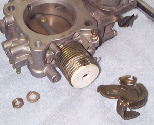
It's now safe to unbolt the two screws that hold the TPS sensor on the TB.
Set both and and the sensor aside.
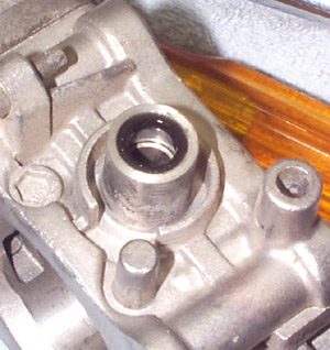
| Gently remove the nut from the end of the TB shaft, that is hidden
under the TPS. Put the nut and washer(s) in a safe place, and remove the
sensor arm (the little metal piece that the nut is holding on). It has a
marking on it to indicate which way is bottom, but make a note of it.
Some years also have a little washer under this piece, so look
carefully. If all is off, you should now be able to see one of the
dreaded seals, first hand! (patience, leave it alone for now) |
 |
 |
The other side, is a little more complex, as it has the throttle cable
connection, and the spring return for the TB.
Make note of which way everything is on there (like the picture) and
remove the nut and washer(s).
Pay VERY CLOSE attention to the springs, and where they hook on.
There are actually two of them, one inside the other. Both have tension
in them, and can bite. Make note of how they hook up, as you will have
to re-assemble it again afterwards.
Suggestion: put a white stripe of whiteout or shop marker across the
springs, in one or more spot. Then, when you go to rewind the springs,
it will help you get the correct tension wound back onto it.
|
| They are wound up, almost two complete revolutions, as you will see
when you start to slide the end off the shaft, and it has a chance to
spin... but you must take them off.
Slide the spring assembly off, and save any washers or bushings that
are on the shaft under it. |
 |
 |
Notepad and marker time again... make some notes, and then label your
actual throttle plate, as to which side is which, and which way up it
goes. Also, make note of which way it tips when it opens. This will help
you when re-assembling, to make sure it's opening identically again.
The screws are screwed in, from the throttle bode elbow side of things,
remember this when re-assembling. |
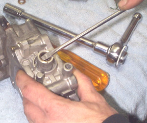
| Tough part now... removing these damn screws.
We used a larger Phillips screwdriver, as you can see. It had a nice
hardened tip, that fit the screws nicely. Pick through your tools, and
find the best match for the screws.
Be careful, the screws are in there very tightly, but they are quite
possible to unscrew and remove, if you're careful. It has also been
observed that they are likely peened (pounded) on the backside to
prevent them from coming loose, which makes it that much harder when you
want to remove them.
One suggestion made by a member out there... was to grind off the
backside of the peened over screws, just to make it easier to remove
without damaging threads. (just use some locktite when you put them
back)
So, remove them.
(the link at the end, has some more good advice on removing them)
The throttle plate screws are pretty hard to get out without screwing
them up.
Some people ended up having to drill one of them out. In case a
replacement is needed, the threaded holes in the throttle shaft are 4mm
x .75 thread. Some used flathead screws with 6mm thread length to
replace the stock screws, and used red locktite. They also cleaned up
the threads in the shaft with a 4mm x .75 tap, because it appears the
stock screws are peened to hold them in place, so they tear up the
threads a little bit when they are removed. |
 |
 |
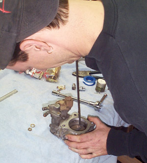
You should then be able to rather easily rotate the shaft, and slide
the throttle plate out of it's slit in the shaft. |
| Once the plate is out, you will be able to easily slide the shaft
cleanly out of the housing. Note from the picture above, which end is
which, but it would be pretty hard to mix them up.
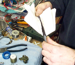
Clean the shaft, with whatever you have available, that is
NON-Abrasive. ie: do not use sandpaper, or emery cloth.
The shaft must remain smooth and clean, but we need to get any
remains of the seal off of the shaft, prior to re-assembly. Some lacquer
thinner or acetone may be your best bet to get any and all residue off
the shaft, particularly where the seals ride on the shaft. |
 |
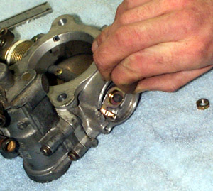
 |
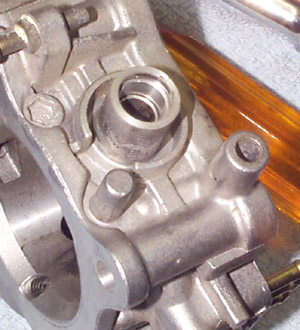
To now finally get the old seal out of each end, put the blunt tip of
a screwdriver, under the metal lip of the old seal and pry it out. It
should just pop right out of the end of the housing.
This metal ring you just popped out, is part of the OLD style shaft
seal, and is no longer needed. Get rid of it. It will not be going back
in.
The new proper seals, have a metal interior for strength, but are
completely encased in rubber, and are a complete replacement for the
stock piece, which was rubber bonded to one side of a metal ring.
(this is not a half-assed o-ring insertion solution)
|
| Once you clean out any and all residue in there, the ends on both
sides should look like the picture here.
If there is any rubber or plastic residue, just clean it out
completely. |
 |
Re-Assembly
Time to start putting it back together.
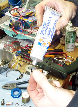 |
Grab some silicone dielectric grease or something similar, to
lubricate the seals and ends of the shaft with. I recommend that you use
silicone dielectric grease, because it is not petroleum based, and will
therefore not tend to harden the new seals prematurely.
When looking at the seals, you will see that they have a solid side,
and an "open" side. The open side should be installed facing
inwards on the TB, on both sides.
Goop them up good, and don't worry if you leave a little on the bore
of the TB when installing them... it will only help. |
| Gently press the gooped up seal, into the outer bore. The solid or
closed side should be facing out towards you. Repeat for the other side
of the TB.
Leave a little extra goop on the bore behind the seal, to assist in
the easy installation of the shaft, and to let any extra settle into the
back side of the seal. |
 |
At this point you should carefully slide the cleaned and polished shaft back
into it's place. Take care as to not disturb the seals you have put in there,
but if the shaft is clean, and maybe even a bit gooped with silicone dielectric
it should slide into place nicely.
Feel free to play with it's rotation at this point, and get the feel for how
clean and smooth it is now rotating within the new seals.
Get the screw holes pointing in the correct direction up, and re-insert the
throttle plate, per your own notes.
 |
With the screws still loose, test the rotation of the shaft, to ensure
that you have correctly re-assembled it per your notes.
It should be opening the same way it was before, and without any
interference from the sides of the TB.
As well, if you hold it up to the light, it should made a good seal
with the sides, when the plate is closed.
Tighten both screws well, when you're happy with them. Really well...
we don't want them coming loose, 'cuz guess where they will end up. You
may want to use some Loc-Tite Blue on the screws, or something similar,
to ensure that they never move again. |
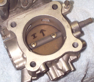
I also want to add, that this last picture is deceptive, as to the rotational
position of the throttle plate, and the arrows on the plate. If you look at
yours, prior to disassembly, and compare it with this picture, you will see that
it cannot rotate as shown in the picture. This is because when I did it the
first time, I didn't follow my own notes, and installed it from the wrong side.
Follow your notes, and you won't have to take it apart again, like I did. (I
didn't think to take another picture!)
Or, as recently suggested to me... there are factory markings on the throttle
plate. These should be on the upper half of the plate, and facing outward
towards the throttle body elbow side.
The Rest
The rest, is pretty much the reverse of disassembly.
So, put things back on, in the reverse to how you removed them.
The spring is two full winds for both, and is a bit of a pain, but quite
possible.
As you reach each point (after the spring in particular) test the operation
of the TB. It should snap shut as it did when you removed it.
Get the TPS back on there, according to your many marks you made on the
housing. Be extremely precise about this, as it's critical to operation... more so
even on the 2G cars, as their Throttle Plate Closed sensor is part of the TPS.
Bolt the sucker back on the intake, with new gaskets if available. The manual
calls for 14 ft-lbs of torque on the main 4 bolts that hold the TB on the car.
You may find it easier to put the ISC motor connector and coolant hoses back on,
prior to bolting up the upper IC pipe again. Throttle cable and TPClosed Sensor
(1G) similarly.
Again, the rest is just the reverse... find everything you took off, and put
it back on again in the correct place.
Gaskets
New gaskets should be used on both sides of the throttle body.
Even with proper gasket prep goo/spray, I personally still found mine to be a
source of another leak, around the gaskets. (it may just be mine, I have a few
oddball parts in there)
So, it's up to you, but I have now replaced my gaskets with a very thin layer
of RTV Ultra Copper (high temp) silicone on both sides. Applied sparingly and
spread with a long Q-tip type applicator. And... it doesn't leak any more.
Conclusion
Now, test for leaks, and you will find that you have none in that area any
more. Now you can focus on the other ones...

The last thought I have, is one of caution. As mentioned, during reassembly,
make sure the throttle plate is operating, and returning to the closed position
firmly, and on it's own. The spring is strong, but if you don't get them both
back wound up twice again, or your plate is mis-aligned, you could run into your
throttle plate sticking open, and NO ONE wants that to ever
happen.
Test it, check it, and double check it after you have tightened everything up
on the car.
Links
Charles Monk, did a fantastic job on another VFAQ, which included the
previous method of using o-rings to fix up the old seals, rather than just
replacing the seals entirely. It's worth giving his entire VFAQ a read, to get
at least one other person's perspective on the removal and disassembly of the
TB.
http://www.plymouthlaser.com/tbor.htm
He also has a good VFAQ on re-adjusting your TPS, just in case you didn't
quite mark it well enough during disassembly and now are having any idle or
deceleration issues.
Thanks to James McElfresh for some good suggestions of corrections and things
to add!
End
Any suggestions, questions, upgrades, improvements? Email
them please.
1990 Model Year DSMs
...are a bit different.
| There are two different sizes. One is the same as above, and the
second one is 8mmx12mmx3mm. |
 |
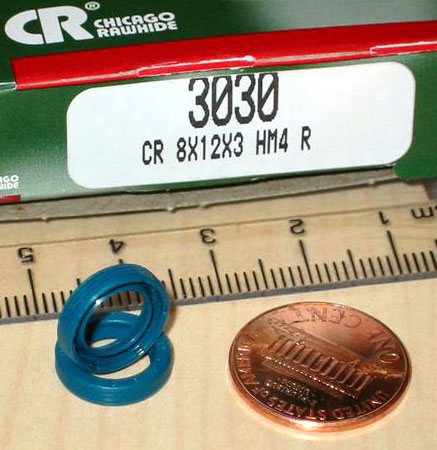 |
There is a seal this size available from Chicago Rawhide as part#
3030. |
| A 1990 throttle body, has quite a few differences that were noticed.
The ISC motor is different, and there is no connector on the TPS sensor
or the ISC motor. Also the throttle body itself is one cast piece
instead of two bolted together. |
 |
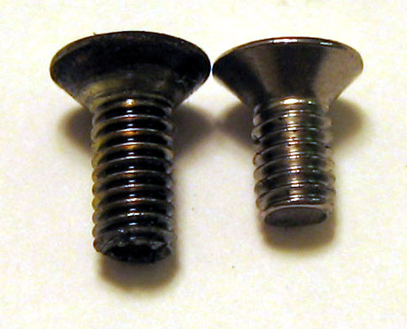 |
The VFAQ says to use replacement screws that are 4mm x .75 with a
6mm thread length. Philip picked up some M4 x .7 with 6mm length and
they were a little short. He then picked up some M4 x .7 with 10mm
length and those look to be an exact match with just enough out the back
to peen them in like the stockers. Not sure if the 90 shaft is thicker. |
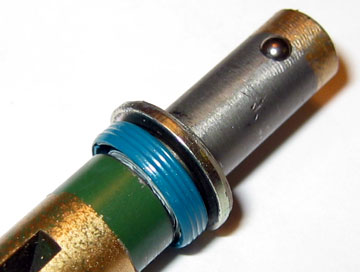
| Shaft with small seal. |
 |