 |
|
Turbo Timer Install in a 2nd Generation DSM |
The basic accepted concept of cooling the turbo in your engine, is to allow your turbo to cool off properly when you stop the car, by feeding it a steady stream of fresh oil, and thus likely preventing coking of the bearings (gunk buildup). Most manufacturers of turbo-charged vehicles recommend idling your car after you get where you're going, for at least 30 seconds, longer if you have really been boosting it. A turbo timer allows you to stop the car, park it, remove the key and lock the door, while a small timer device keeps your engine running for a pre-set period of time.
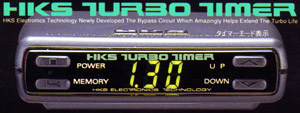
The two most common units on the market are the Greddy Turbo Timer and the HKS Turbo
Timer IV. Selection is up to you.
When it came time for me to buy one, the HKS unit was slightly more expensive. But, HKS
did promise that their unit, when used with their wiring harness for the 2nd Gen DSMs,
with some minor mods, would fully function with the factory alarm system. This was very
important to me, so I have selected the HKS unit, and will discuss it from here on in. The
Greddy install is probably very similar, however I have no experience with their
particular unit.
|
|
If someone tries to tell you that the Greddy harness is just as good, and a few bucks less, you'll get what you pay for. Remember that when I tell you to cut the blue wire, and your Greddy harness wires are all the same colour.
As to full functionality, it presently operates in the following manner:
First things first... I/We can in no way accept responsibility for what you may do to your car. We will simply try and explain how we installed the thing here, on a 1997 Eagle Talon TSi AWD, with a factory alarm system, with keyless entry. You shouldn't have any problems, but you know what Mr. Murphy said about problems... this install also assumes that you have the factory alarm system, so if you don't, you may not need all of these steps in order to have full functionality.
You'll need the usual tools to get your trim panels off, a set of wire cutters, a set of pliers, and some electrical tape. Relax, the tape is just to cover the end of a wire, it's not for some goofy hack job. I have a love for my car, and I try and do everything I can to keep it looking perfect.
The HKS Turbo Timer IV (hereafter known as the TT) comes with an assortment of wire splices, that don't require you to snip or strip wires in order to make a connection. Have a look at one, play with it, you should be able to figure out just how it works. The one side is for the wire you are tapping into, the other (the one with the little divider in the middle) is for the wire you are bringing in. You put the one side on the through wire, shove the new wire in the other side, and snap the metal piece through both of them with the pliers. Then snap the cover closed to protect the circuit from shorting out.
Remove the three screws that hold the steering column cover on. They are on the underside of the cover. Remove the cover.
Right in front of you there should now be the main moulded blue ignition plug. Separate the plugs from each other, and you will see that they match the HKS harness perfectly... one male, one female. Match them up and plug them both in. So far, this is all the same as the basic instructions that come with the HKS TT unit.
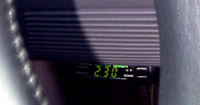
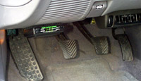
Many and varied are the locations for the TT unit itself. Some prefer it up on top of the steering column, some have cut holes in the dash. I personally used the supplied sticky Velcro and attached it underneath the dash, just above the clutch pedal. In this location, it is easy to see, reachable, but out of sight and distraction while driving, as can be seen here.
 |
 |
|
 |
Plug the TT plug that matches up with the aforementioned harness, into said harness. Run the black wire from the TT to a nearby frame ground on the car. A metal screw that screws into metal frame is required here.
Next, route the remaining grey wire through the underside of the dash and over to the radio area. Remove the ashtray and the cup holder by simply pulling up on them. You can then remove the rest of that whole trim assembly by pulling up on it. It just snaps into place. Once this is removed, you will see the parking brake assembly and switch. There is only one wire coming from it, this is the one you want. Use one of those wonderful crimp connectors we talked about earlier, and connect your grey wire to this single wire. Use some of the supplied tie-wraps to make sure that the grey wire does not get tangled up into anything else.
At this point, you are ready to run, without the alarm. Check your connections, and give it a test, as per the HKS instructions sheet. If you have no factory alarm system, then just put the covers back on at this point and carry on driving!
For those of us who have a factory alarm however, there is a bit more to do. Some of it is not easy, but in the end it all works, so the ends justify the means, right?
You can go ahead and put the ashtray, cupholder etc back in, assuming that the parking brake safety is working ok, per the test instructions from HKS. (basically meaning that it does what I described above)
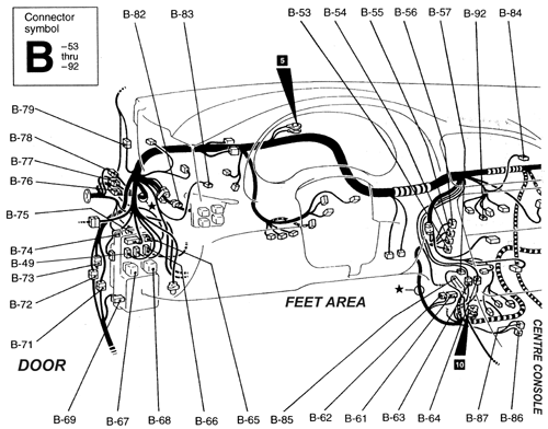
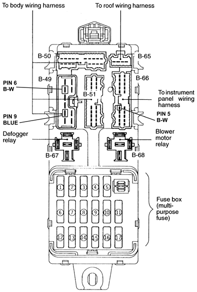
To begin with, we must locate a few items. If you can translate this diagram to the car's layout, then you're half way there. Get down on your knees and peer up under the dash to the left of the clutch and up. You're looking for the fuseblock and relay assembly. Remove whatever panels and covers you feel are necessary to get to the wires on this unit. You may also find that removing the relays labeled B-67 and B-68 help gaining access. Peel back some of the electrical tape on the wire bundles leading to B-49 and B-66, so that you can get at the wires more easily.
First things first, we should check which wires we're looking for.
Pull off connector B-49 and get a volt meter.
Put the negative lead on a solid ground point on the frame.
Put the positive lead into pin 9 (blue wire) of the B-49 connector you just pulled out.
Turn the ignition to the ACC position, and the meter should read battery voltage (~12v).
Then, put the positive lead on pin 6 (black with white stripe) of the B-49 connector
you just pulled out.
Turn the ignition to the ON position, and the meter should read battery voltage (~12v).
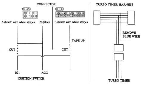
Keep in mind, that all PIN# references we are making, are to the pins that the wire plugs into on the fuseblock. This applies to both B-49, and to B-66 which we will address shortly. Just like the diagram shows to the right.
At this point, you should disconnect the negative battery terminal for safety sake, and plug B-49 back in.
Cut the wire leading to pin 6 (black with white stripe) on B-49. Be sure and leave yourself enough length attached to B-49, so as to be able to reach pin 9 (blue) of B-49, and be able to use it with one of those handy-dandy snap crimp connectors. Take the part of the pin 6 wire that is going into the B-49 connector, and splice it into the pin 9 wire, without cutting the pin 9 wire. Leave the other half of the pin 6 wire dangling, we'll use it again later.
Now, in order to make sure that the brake circuit has power, so as to be able to engage the safety circuit, we must make one more connection.
On plug B-66, snip the wire going to pin 5 (black with white stripe), and tape up the part going into the B-66 plug.
Take the remaining piece, and connect it (either with a butt crimp connector or with our handy-dandy connectors) to the wire we left dangling from pin 6 of B-49 (discussed above).
You can now put back the relays and anything else you removed from the fuseblock.
Go now to the HKS TT Harness, the one we put between the two stock plugs at the beginning. Find the blue wire in this harness that runs to the TT unit itself (and only to the TT, not between the ignition plugs), and snip it. Tape up both ends.
That should be it.
That's about it. After that, mine has worked great to this day.
Please, if I have missed anything at all, feel free to email with suggestions, comments, additions, etc. Thanks to Club DSM Canada for hosting this information!
Good Luck!